My family has an annual reunion where a lot of games are played, many of them revolving around their favorite sport: soccer. Some twenty years ago my father came up with the question of whether we could measure the speed of a soccer ball. That way we would have a new game in which the family members could see who has the strongest kick. Since then this project has seen several incarnations.
The first incarnation was programmed on a Commodore 64 computer. We dug a push-button switch into the ground and placed the ball on top of it. When the switch was depressed a timer would start. A pull switch connected to the net in the goal would be used to detect the arrival of the ball and stop the timer. By dividing the distance between the first switch and the net by the elapsed time we obtained the speed of the ball. Of course, because the speed was measured by the computer I could build a program around it that would keep track of the ranking and the high-score of each participant.
This setup worked pretty well, but it had some drawbacks. The switch on which we placed the ball had to take a lot of punishment; it would get clogged up with dirt, and, as the contestants focused more and more on power and less and less on accuracy, it happened that it flew along with the ball instead of staying in the ground. Also the younger contestants could not kick the ball hard enough to trigger the switch in the net, so we had to help them a little by pulling the net when the ball arrived. To encourage them we could pull the net a bit early to increase the speed, but a little misjudgment in timing quickly sent a four year old nephew to the top of the rankings with a speed of over 200kph 🙂
The switch used to trigger the net never changed, but everything else did.
The switch on which we placed the ball was the first to be replaced. We replaced it by a Plexiglas plate with a light sensitive resistor beneath it. This solved the problem of dirt getting into the switch. There were some problems with this setup though; we had no analog input, so we could not easily measure the resistance of the sensor. We solved this using a schematic from B. Kainka’s “PC poorten anders benut”. The circuit basically measures the resistance by measuring the time it takes to charge a capacitor. However, this solution does decrease the accuracy of the system somewhat.
Another reduction of the accuracy occurred when we switched (as the title of Kainka’s book implies) to a PC, since the multi-tasking Windows 95 operating system of that time was not known for its predictable response times to interrupts. On the other hand the whole system now consisted of a single laptop, some simple components and a few long wires, and it was fun to play. It wasn’t too long before somebody cracked the plexiglass plate, however.
About a year back we hear that it’s our turn again to organize the family reunion of 2009. It seemed like a good idea to bring back the system, so I started thinking. I learned a bit about electrical circuits since I made the last version in the nineties, and I thought it would be fun to make a small self contained system that could measure the speed of the soccer ball. That way it could run on batteries. (Technically the laptop ran on batteries, but it was an old laptop and the batteries did not last for more than half an hour, so we always needed an extension cord.) Furthermore, I always wanted to try to design and implement a circuit involving a micro-controller, and this seemed like a good opportunity.
The pull-switch in the net remained as it was (all the little nieces and nephews have all grown up by now). The switch to detect when the ball was kicked had to be altered though. Nothing that made contact or even came near the ball would do. So, I opted for a IR gate. I considered this design, but then I found the Velleman MK120 kit. The Velleman kit seemed easier to assemble and came with all the parts, including a PCB.
I modified the MK120 kit a bit though. The kit consists of a separate IR transmitter and a receiver, both running on their own battery. I wanted only a single battery in the whole system, so that there could only be one depleted battery that causes problems. Besides, I would have to run a cable anyway for the gate’s signal to the project’s main housing.
I placed the transmitter and receiver in the same housing, so that they could draw their power through the same cable. To get the signal from the transmitter to the receiver (and to interrupt the signal if a soccer ball passed by) I used a reflector from a bicycle. This reduced the maximum size of the gate, but it was still sufficient to pass a soccer ball with a considerable margin. Besides, since the gate now consisted of a single box with the electronics and a reflector, instead of two boxes with electronics, the risk of a stray ball damaging the electronics was minimized.
Note that I used a reflector because it has an interesting property: it always reflects light back towards its source, as opposed to a mirror which reflects light such that the angle of reflection equals the angle of incidence. So, a mirror would have to be finely tuned to reflect the infrared light from the transmitter to the receiver, whereas a reflector will do this pretty much automatically.
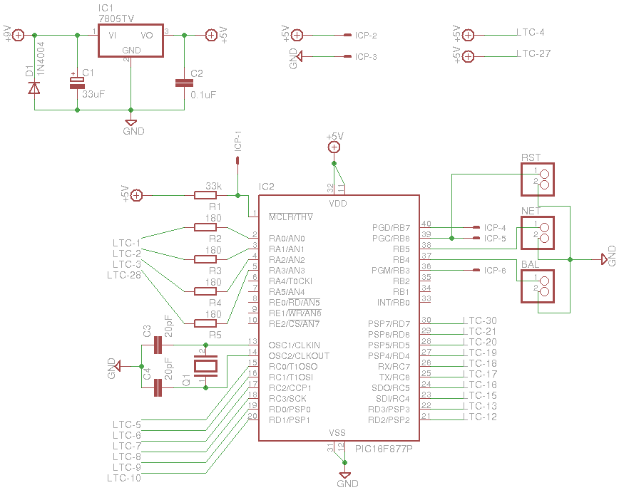
The circuit in the main housing was pretty straightforward. There is a voltage regulator to reduce 9 volts to 5 volts, because the MK120 runs on 9V and the PIC processor runs on 5V. The LTC-637 display was obtained from an old alarm clock. To my surprise I even found the data sheet for it. The PIC micro-controller is a actually a 16F77 instead of the 16F877 indicated in the diagram. The 16F877 has some more advanced features, but I did not need them for this project.
So, after some work the result was:
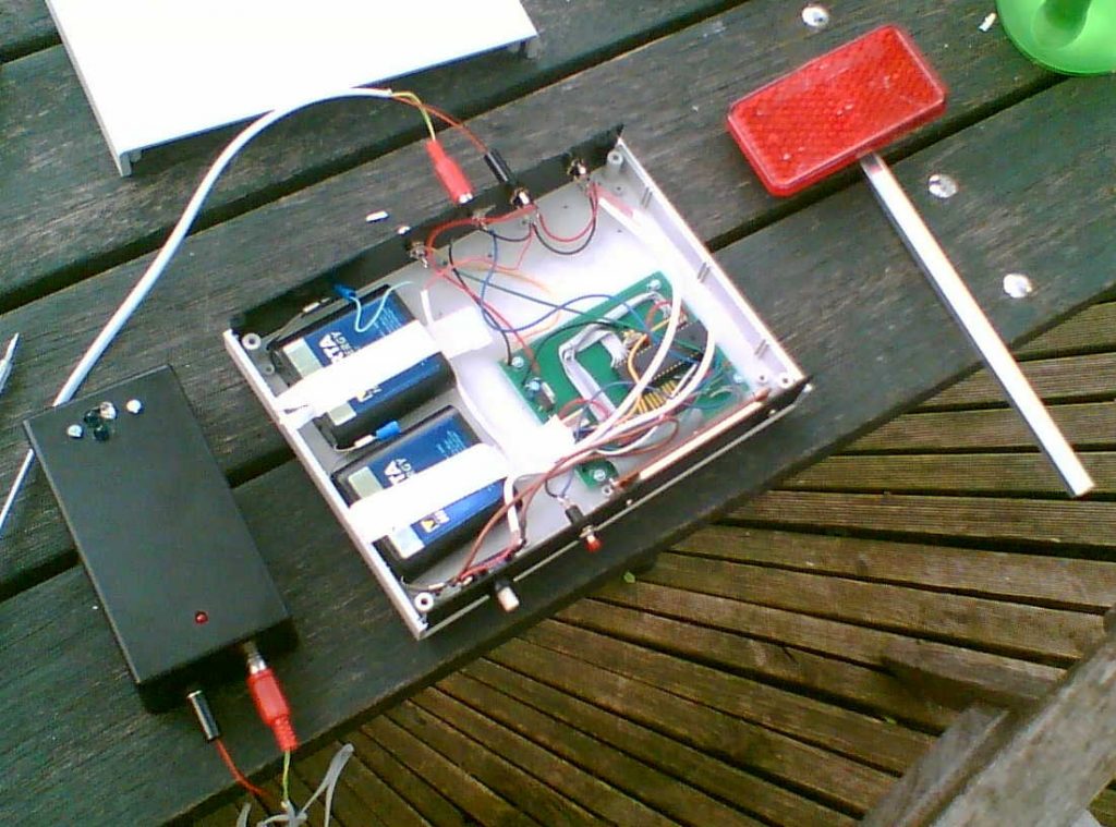
The black box on the left contains the MK120 kit. The two blue LEDs are the infrared LEDs of the transmitter part and the white LED-like component is the fotodiode of the receiver. As you can see they are pretty close together. It took some fidgeting to make sure the light from the transmitter would not go directly into the receiver, resulting in unreliable operation of the gate. The red LED on the bottom of the box is exactly that, a LED. It lights up when the beam of IR light is broken. This is very useful when debugging and setting up the gate, and it taught me that a hand reflects enough IR light to make the beam appear unbroken when it is held close enough to the sensor (that was a bit confusing at first :)).
Since there was enough room in the main housing, I used two 4.5-volt batteries to obtain 9 volts instead of a single small 9-volt battery. This way the system should be able to run at least a full day non-stop without depleting its battery. To be on the safe side, however, I included a power jack in the back so that we could always plug in a 9V adapter, should the batteries fail.
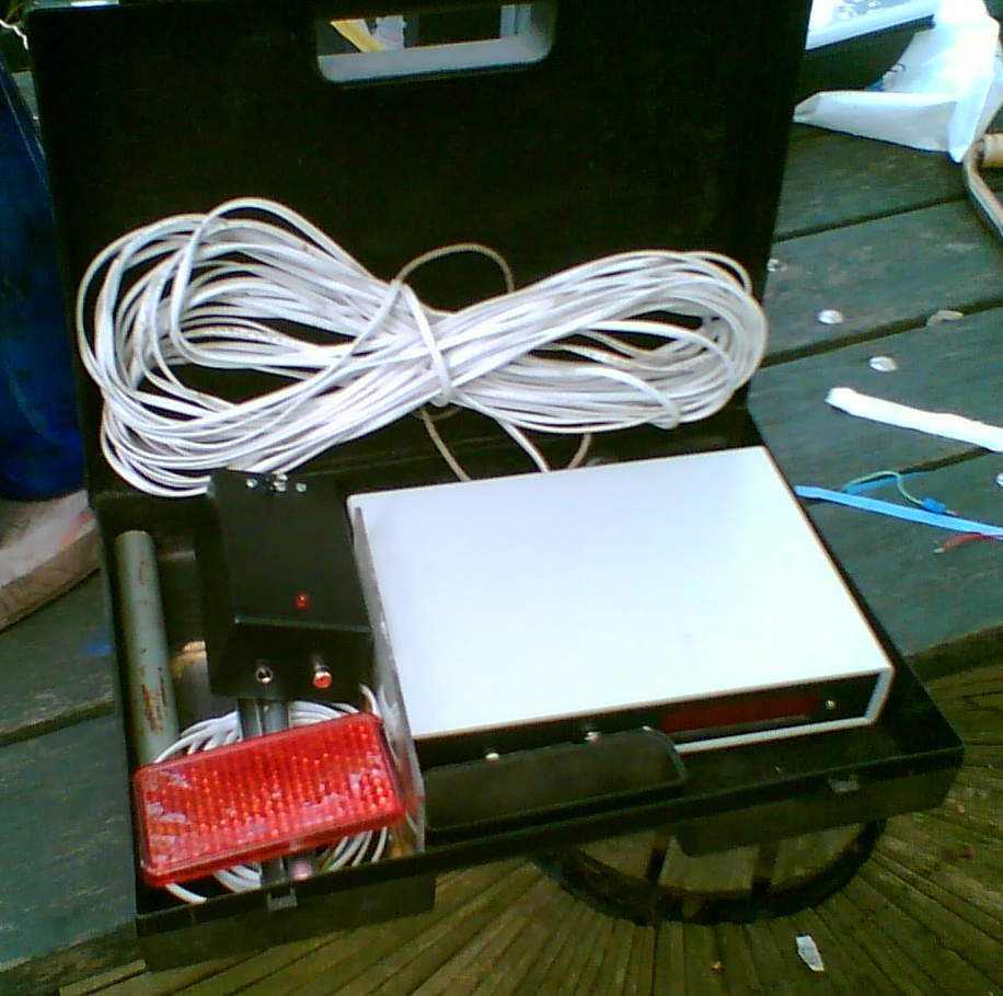
As you can see everything fitted inside a small plastic suitcase:
The system had its first real test during the 2009 soccer camp. The only problem was that the display was hard to read in the sunlight. I increased the brightness of the display by replacing R2-R5 with lower values. Although this did help a bit, it was not enough.
So, for the next incarnation I’m going to see if I can use some palm-sized 7-segment displays or something, but that will have to wait until after the family reunion.