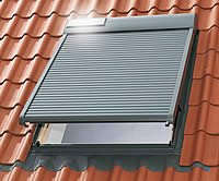
For the new bathroom in my home I also installed a Velux window, complete with an electric roller shutter. Of course I wanted to connect this shutter to the rest of my home automation system. Velux has options for this, but I wasn’t looking forward to integrating a vendor specific system to my existing setup. I already had Z-wave installed so I made a small project to connect the Velux shutter to a Düwi Z-wave module.
The problem in connecting the two is as follows:
The Velux electric roller shutter works on 24VDC and has two wires connected to it. Connecting the wires in one way to 24VDC moves the shutter up, and reversing the polarity moves the shutter down. The Düwi Z-wave module, on the other hand, connects one of its outputs to a common input when the shutter should go up, and connects another of its outputs to the common input when the shutter should go down. So there is no simple way to connect them together and get a functioning system.
On the plus side, the Düwi module could take 24VDC on its common input even though it operates at 230VAC, and the Velux shutter automatically stops when it reaches its extreme positions, i.e. open or closed. So that could simplify things a bit.
Oh, one thing that I (fortunately) did not have to test is that the Velux shutter is actually really “smart” and starts behaving differently once it has been connected to an official Velux controller. At that point it (apparently) no longer responds to the polarity of the 24VDC, but expects some more complicated protocol, even after it is disconnected.
In any case, my first idea was to simply get a transformer that outputs 24VDC and then make a small circuit out of relays to convert the output of the Düwi module into something that can be connected to the Velux shutter. But I wasn’t looking forward to having the transformer plugged in 24/7; it will draw power, even when the shutter is not moving. So I made the circuit a bit more intricate, now only the Düwi module draws power, and the transformer is only powered when the shutter has to move:
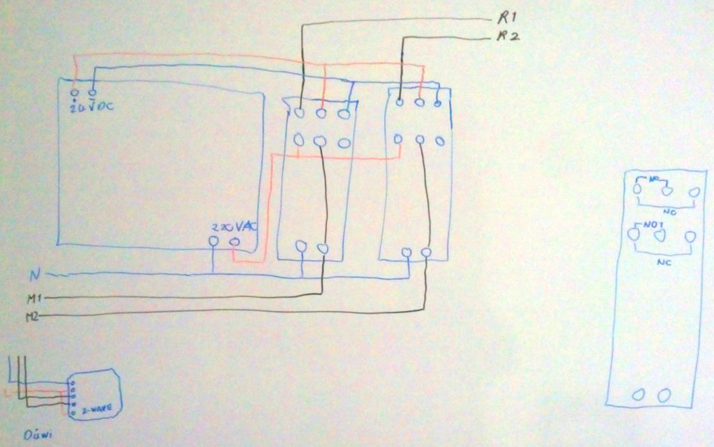
So the outputs of the Z-wave modules (M1 and M2) are used to power the relay. Furthermore these outputs are connected to one of the NO contacts of each relay, so that the transformer is powered when either M1 or M2 is live. The other poles of the relay are used to connect the output of the transformer to the inputs of the Velux shutter (R1 and R2).
Note that if M1 is live, then R1 will be connected to +24VDC and R2 will remain connected to ground.
Vice versa, if M2 is live, then R1 will remain connected to ground, while R2 will be connected to +24VDC.
The components used in this little project were:
- Transformer: 230VAC in to 24VDC, 600mA out (Netvoedingmodule 24V 600mA BS (Conrad Electronic))
- 2 Relays: 230VAC with two switching contacts, i.e. DPDT (Printplaat relais 230VAC (Conrad Electronic))
- Düwi blind control module with Z-Wave.ME firmware
- Some cabling and an AC power plug
- A box to house everything in (Strapubox Schalenbehuizing ABS (b x h x d) 230 x 62 x 130 mm Zwart (Conrad Electronic))
- Some stuff to keep everything in place: